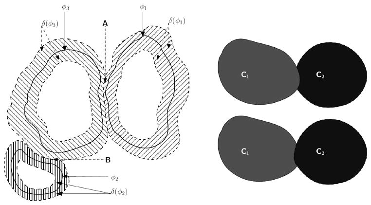
Fig. 3.

[Left]Narrow-band fronts of cells belonging to three different “colors”. The corresponding zero level set curves are given by φ1 (“red”), φ2 (“green”), and φ3 (“blue”), with the narrow bands given by the region where δ(φi) > sthresh. At region A, the narrow band of the “red-colored” cell intersects with the narrow band of the “blue-colored” cell. We enforce an explicit rule that the narrow band of a cell, φi that is currently being updated cannot overlap with a different colored cell (i.e., (φj)). Hence, in region A, the narrow-band of the “red-colored” cell (i.e., δ(φ1) > sthresh does not include those areas for which φ3 ≥ 0. A similar rule is applied when updating the “blue-colored” cell, at region B. [Right] If a “collision” occurs between cells (i.e., δ(φi) = δ(φj), i ≠ j), then depending on which order the level sets are updated, we may get either C1 protruding into C2 or vice-versa.
