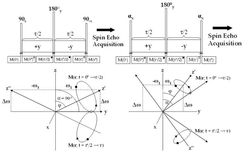
Figure 3.

ΔB0 insensitive (A) and B1 and ΔB0 insensitive (B) composite pulses for T1ρ weighted imaging and the magnetization path during each sequence. In (A) magnetization is flipped along the y-axis (grey), where it nutates about the effective field (z′-axis) and at time τ/2 (black) is flipped 180° about the y-axis where it nutates around the effective field (z″-axis) back along the y-axis (grey). In (B) the magnetization follows a similar path, but with two differences: (1) the excitation flip angle does not need to be 90° and (2) B1 insensitivity is maintained by flipping the magnetization along the −z-axis. While (B) is more robust than (A), an imperfect 180° flip can still produce artifacts.
