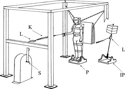
Figure 1. The apparatus.
Only the main components have been labelled. The substantial steel frame acted to anchor all the components. The subject stood on a platform (P) supported on ball bearings at ankle height. The platform was rigidly attached to a plywood backboard to which the subject was tied by Velcro straps at knee, thigh, waist, shoulder and head height. Forward collapse was prevented by the safely chains. The subject is shown in the forward position (approximately upright); the chains are tight. Rearward fall was limited by a mattress which the backboard contacted at approximately 10 deg tilt. In hand balancing, the subject could balance between these limits by pulling on the handle which was attached through the spring (K) and in-line load cell (L) to the rigid frame. In motor balancing, a small hand held joystick was operated to controll the position of the servomotor (S). The output of this device was then coupled through the spring and in-line load cell to a linkage attached to the backboard at approximately waist height (not shown). In inverted pendulum balancing the artificial load (IP) was substituted for the subject. The necessary force to balance it was exerted via the spring by the subject (who now stood in a position close to the servomotor and was supported by the frame) either manually in hand balancing or by the servomotor in motor balancing. In both situations, force was again measured by the in-line load cell (L). Visual registration of body or pendulum angle could be enhanced by a cathode ray tube (CRT) display mounted 1 m in front of the subject.

