
Figure 1.
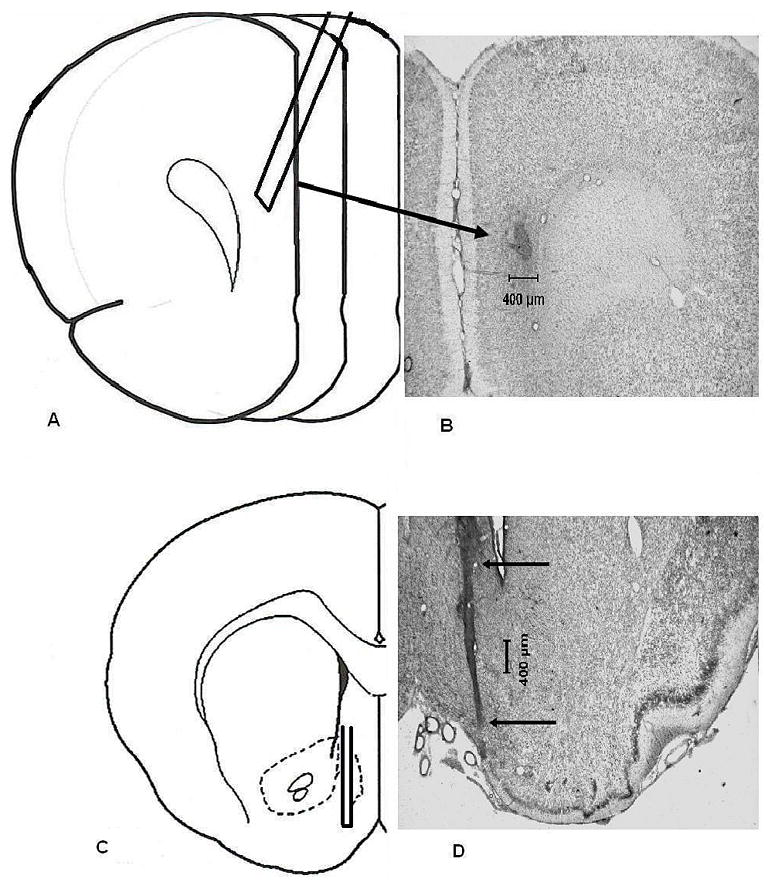
Representative histology for mPFC and NAC shell probe placements. (Panel A) a schematic depiction of a mPFC placement. Guides were implanted so that when probes were inserted, the membrane tip (3.0 mm) was located at AP +4.2, LM +0.6, DV −0.6 from dura pointing 20° rostral. (Panel B) a representative photomicrograph from a subject with the mPFC placement that is illustrated in panel A. Due to the angle at which the guide cannula and probe were positioned, the arrow points to the site of termination of the dialysis probe. (Panel C) a schematic depiction of a NAC shell placement. Guides were implanted so that when probes were inserted, the membrane tip (2.0 mm ) was located at AP + 1.3, LM +1.0, DV −5.8 from dura mater. (Panel D) a representative photomicrograph from a subject with the NAC shell placement illustrated in panel C. The arrows indicate the tract of the guide cannula. All coordinates were based upon Paxinos and Watson (1998).