FIG. 8.

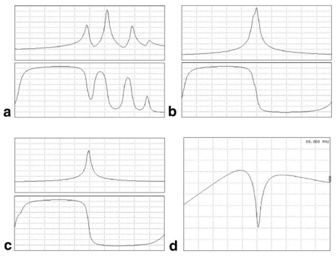
a: Impedance spectrum of a coupled four-element LPSA, as seen from the outside channel 1 (top spectrum, magnitude, 50Ω/div; bottom spectrum, phase, 20°/div). b: Spectrum with interconnecting capacitors for decoupling (magnitude, 5Ω/div at top; phase, 20°/div at bottom). c: Spectrum with interconnecting capacitors and channel 4 shorted (magnitude, 5Ω/div at top; phase, 20°/div at bottom) for decoupling. This is equivalent to a low-input impedance preamplifier. d: S21 for a nearest RTL pair. Dip is approximately −26 dB. The horizontal axes are frequency-centered on 63.87 MHz, with a span of 10 MHz.
