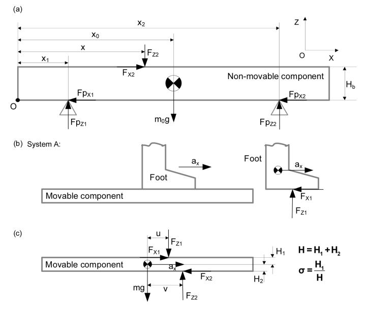
Fig. 1.
Free-body diagrams of (a) the non-movable component in the inertial reference frame with an origin at point O, (b) system A, which includes the foot and the movable component, and (c) the movable component of the slip inducing device. The foot and movable component travel the same motion in the X direction. The forces acting on system A, Fx2 and Fz2, can be derived from measurements from the two force platforms, FPx1, FPx2, FPz1, and FPz2. Because the connections between the non-movable component and the force platforms are point and hinge contact, moments are negligible. The horizontal component of the acceleration of the movable component is ax. Not shown in (c) are xcoM and xcoP, the X-coordinates of the movable component's center of mass (COM) and the corrected center of pressure (COP) acting on the person with respect to the origin, O. The COP offset (u−v) represents the amount of correction needed by relating the measured COP, v, to the corrected COP, u, with respect to the COM. X and Z axes represent the directions of anteroposterior and vertical, respectively.

