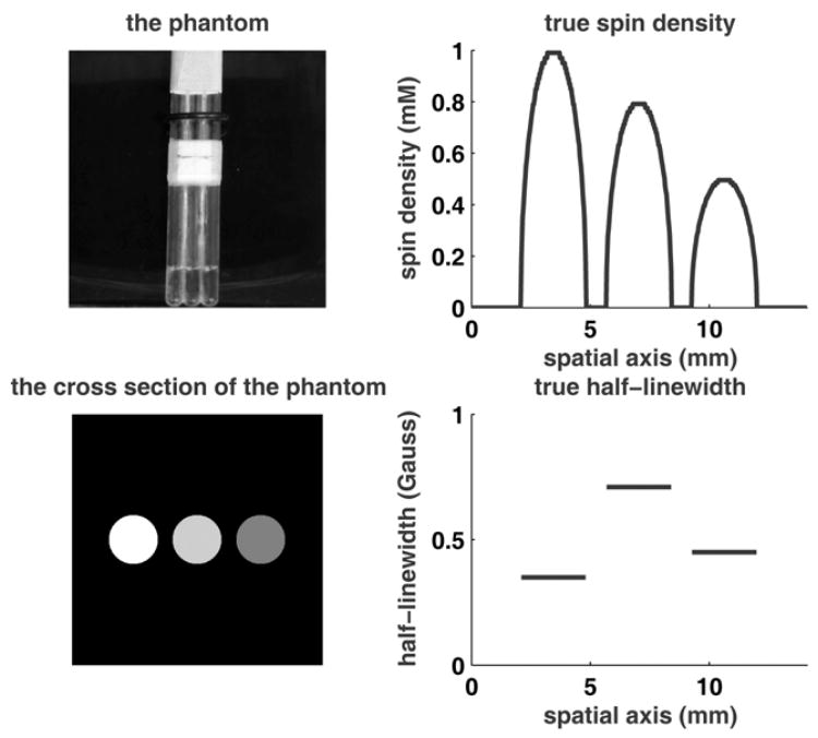
Fig. 7.

The phantom used for experiment. Top-left: Photograph of the phantom; the three tubes are glued together and filled with nitroxide solutions with three different concentrations mixed with different amounts of the broadening agent. Bottom-left: Schematic of the cross-section of the inner perimeters of the tubes. The magnetic field gradient is along the horizontal axis. Top-right: Spin density profile. Bottom-right: Half-linewidth profile.
