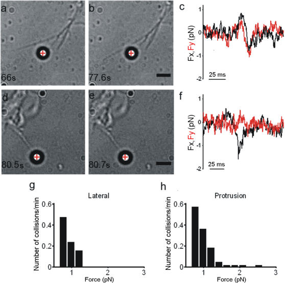
Figure 2. Force exerted by Filopodia.
(a–b) Lateral collision between a filopodium and a trapped bead. Trap stiffness was 0.008 pN nm−1. The red cross indicates the bead's equilibrium position inside the optical trap. (c) Fx and Fy from the QPD during the lateral collision shown in (a–b). (d–e) Collision between a protruding filopodium and a trapped bead. (f) Fx and Fy from the QPD during the filopodial protrusion shown in (d–e). Trap stiffness was 0.008 pN nm−1. (g–h) Histograms of forces measured during lateral collisions and protrusions. Data were collected from 75 experiments, each lasting 2 min. Scale bar, 2 µm.

