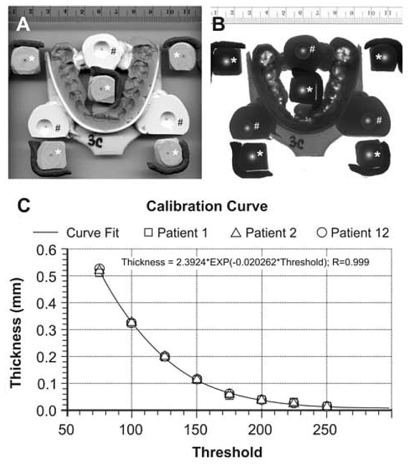
Fig. 1.

Calibration of transillumination brightness to impression material thickness. Images of a MIP record, impressions of 8 ball bearings in contact with a flat plane, and a scale scanned at 300 dpi in a Hewlett Packard ScanJet 5370C using reflective lighting (A) and the ScanJet XPA Transparency Light (B). Light regions on the transilluminated image (B) represent thin regions of the record. The five sphere-to-plane impressions with the plane side visible (*) provided calibration points for calculating record thickness. The three sphere-to-plane impressions with the sphere side visible (#) are reference points for maintaining alignment between the two sides of the record while constructing its 3D virtual image. The calibration curve for converting brightness to thickness (C) shows data for three subjects; however, all twelve were used in deriving the best fit calibration curve.
