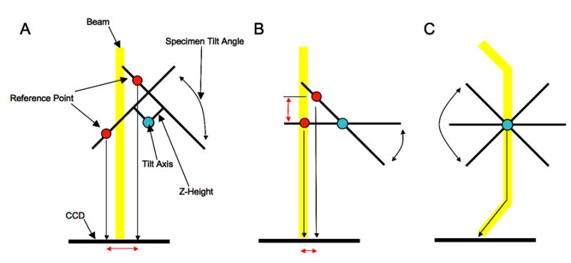
Figure 2.

The three panels illustrate the microscope z-height and optical axis alignment that is performed prior to automated collection of RCT or OTR data. Panel A shows the image translation (red arrow) seen when the microscope z-height is set incorrectly and the stage is tilted to either side of 0°. By measuring this displacement it is possible to correct the z-height regardless of the position of the optical axis. Panel B shows the microscope when the z-height is set correctly but the tilt axis is misaligned with the optical axis. This misalignment manifests itself, as shown, as another image displacement and defocus change when the stage is tilted away from 0°. Since this alignment has no effect when the stage remains at 0° it is commonly ignored in standard data collection. Fortunately it can be corrected electronically by using an image shift adjustment to compensate. Panel C shows the final aligned state where sample remains within a consistent focal plane regardless of tilt angle or stage movement (stage movements translate the specimen along the tilt plane).
