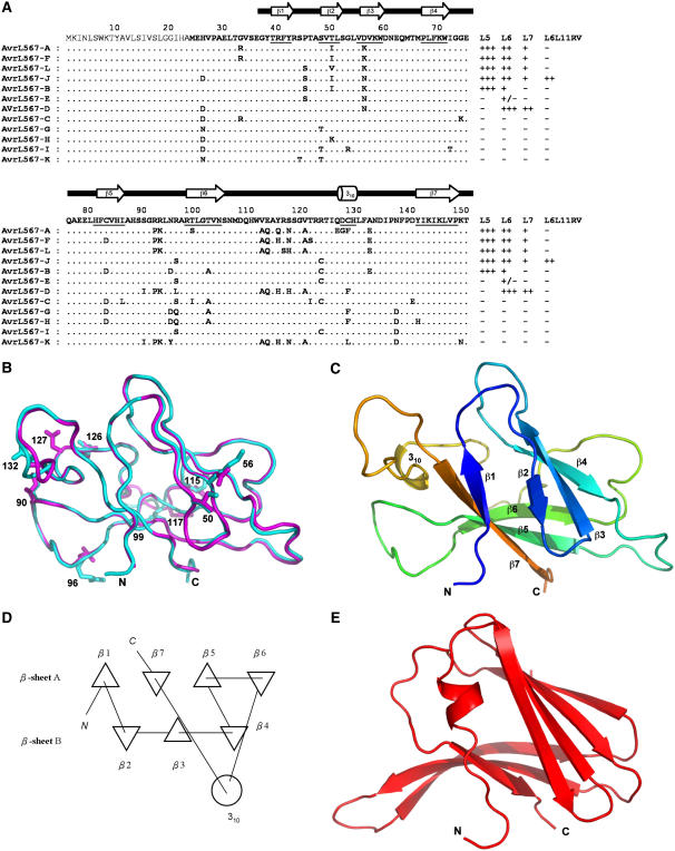
Figure 1.
Structures of AvrL567-A and AvrL567-D Proteins.
(A) Sequence alignment of the known members of the AvrL567 family. Secondary structural elements, based on the structure of AvrL567-A and assigned with the program DSSP (Kabsch and Sander, 1983), are indicated above the sequence and by underlining the sequence. The top row shows the consensus sequence. The signal peptide, shown in thinner font, was not included in the construct used for structure determination. The final columns indicate whether a necrotic response was observed when these proteins were expressed in flax lines containing L5, L6, L7, or the recombinant L6L11RV gene (Dodds et al., 2006). +++ indicates a very strong necrotic response observed within 4 d, ++ indicates necrosis observed within 10 d, + indicates a chlorotic response observed after 10 d, +/− indicates a slight chlorotic response in some but not all assays, and − indicates no response observed.
(B) Superposition of the structures of AvrL567-A (cyan) and AvrL567-D (magenta). The backbones of the proteins are shown in a coil representation, and the side chains of the 10 residues present in the models that differ between the two proteins are shown in a stick representation. This and other structure diagrams were prepared using PyMol (DeLano Scientific).
(C) Ribbon diagram of the structure of AvrL567-A. The β-strands are indicated by arrows and the 310-helix by a coil. The color changes continuously from the N terminus to the C terminus (blue to green and yellow to red).
(D) Schematic diagram of the connectivities of secondary structural elements in AvrL567-A. Triangles represent β-strands, and the circle represents the helix. This was prepared using TOPS (Michalopoulos et al., 2004).
(E) Ribbon diagram of the structure of ToxA (Sarma et al., 2005) after superposition onto AvrL567-A in the orientation shown in (C). The secondary structure elements are shown as in (C).

