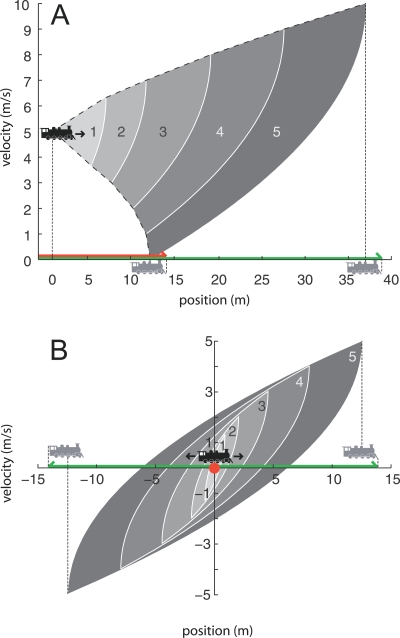
Figure 4. Phase Planes Illustrating the Time-Limited Reachable Set, Time-Limited Motor Volume, and Stopping Motor Volume for a Locomotive Moving on a Train Track from Two Initial Velocities.
Filled sectors and dashed curves refer to states for the locomotive's center of mass. The red line/dot indicates the stopping volume for the locomotive; the green line indicates the time-limited motor volume for t ≤ 5 s. Both are inclusive of the locomotive surface as indicated by the gray locomotives. (A) x 0= (0 m, 5 m/s). Upper and lower curved dashed lines represent constant acceleration (+1 m/s2) and deceleration (−1 m/s2). Overlapping filled sectors represent reachable sets for time up to and including the labeled times, in seconds. (B) x 0 = (0 m, 0 m/s).

