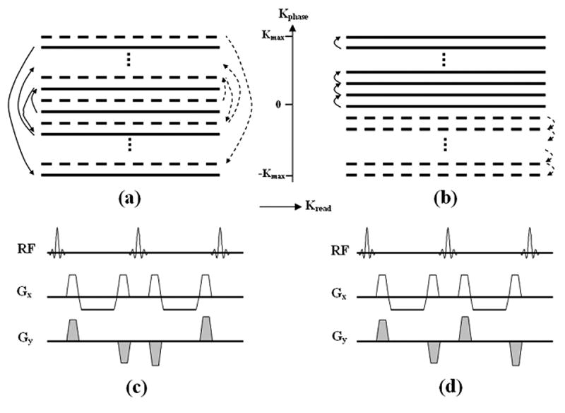
Figure 1.

Schematic of the k-space trajectory of the conventional ACE (a) and proposed LCE (b) PE orders. K-space data of one imaging slice is filled by interleaving two segments in this example. The trajectory of ACE scheme moves from central to outer lines in the PE direction and alternates between positive and negative regions in each segment as illustrated by two segments (1st: solid line, 2nd: dashed line) in figure (a). Note the sign as well as the magnitude of the PE gradient (Gy) alternates from one RF cycle to another (Fig.c). Using LCE PE order, the k-space trajectory travels uni-directionally from central to outer lines in each segment as illustrate in (b). The magnitude of Gy is slightly increased from RF cycle to another. Polarity of gradient pairs remains unchanged in the whole readout train as shown in (d).
