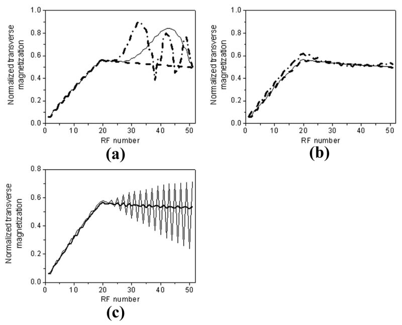
Figure 3.

Simulated transverse magnetization in one readout train with three different phase error steps (Δφ = 0°, 0.3°, and 1°). 20 linear ramp-ups are applied before data readout. Using conventional centric-encoding (a) PE order, signal oscillation increases with phase error step, as indicated by increased signal fluctuation from 0° (dashed line) to 0.3° (solid line), and 1° (dash-dotted line) in the figure. In comparison, linear-encoding order (b) shows improved signal stability with phase errors. Signal fluctuation is relatively small even with phase error step as high as 1°. Note the signal stability is related to local frequency offset. As illustrated in (c), strong signal oscillation is expected with a 30 Hz frequency offset and 0.3° phase error step using centric-encoding scheme (thin line). Linear-encoding shows much better tolerance to off-resonance in contrast. Signal fluctuation is very small indicated by thick line in (c). Parameters for simulation include: 20 linear ramp-ups, TR/TE = 3.2/1.6 msec, flip angle = 70°, 124 phase-encoding lines, 31 lines per heart beat, T1/T2 = 1200/250 msec.
