
Fig. 10.
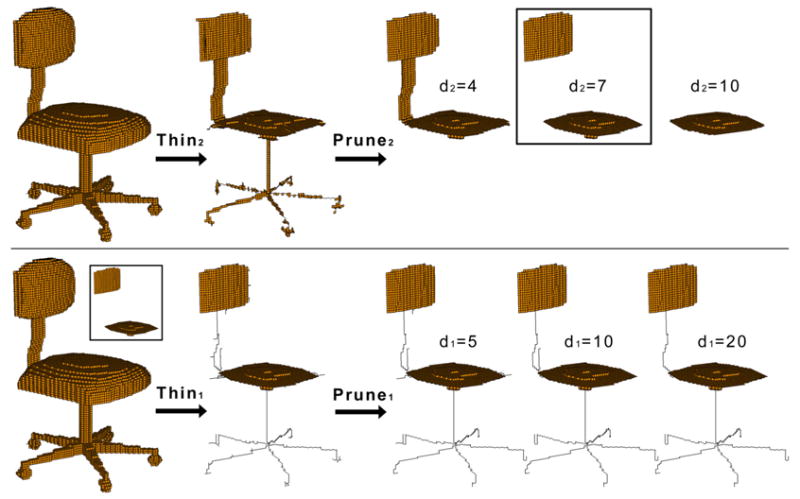
Stage 1 (top) and 2 (bottom) in generating a skeleton. In the second stage, d2 = 7 is used as input while several values of d1 are tested. Note that in the second stage, curve thinning preserves the surfaces (shown in the insert) computed by the first stage.