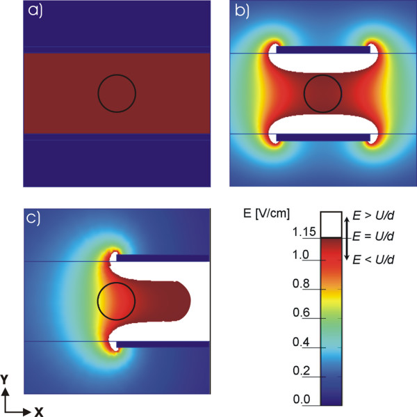
Figure 3.

Calculated electric field distribution for the geometries with parallel plate electrodes. Numerical results of the electric field distribution for geometries defined in Fig. 1: a) the infinite plate electrodes case, b) the target tissue symmetrically placed between the finite plate electrodes and c) the non-symmetrical example when the target tissue is not entirely in-between the finite plate electrodes. The circle represents the target tissue e.g. tumor tissue and the white region represents part of tissue where E ≥ U/d.
