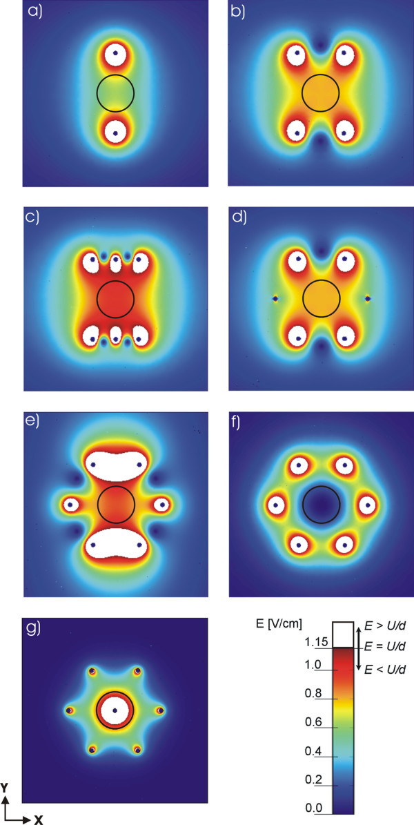
Figure 4.

Calculated electric field distribution for different needle electrode configurations. Numerical results of the electric field distribution for the geometries defined in Fig. 2: a) two needle electrodes, b) four needle electrodes, c) six needle electrodes in two rows, d) six electrodes placed in a circle with polarities as shown in Fig. 2d, e) six needle electrodes placed in a circle with polarities as shown in Fig. 2e, f) seven needle electrodes placed in a circle – using alternating polarities seven needle electrodes placed in a circle – with central positive and surrounding electrodes having negative polarities and g) seven needle electrodes placed in a circle – with central positive and surrounding electrodes having negative polarities. In all cases the applied voltage was set in such a way that U/d = 1.15 V/cm, where d = 8.66 mm for Figs. 4a, 4b, 4c, 4d and 4e and d = 5 mm for Figs. 4f and 4g. The circle represents the target tissue and the white region represents part of tissue where E ≥ U/d.
