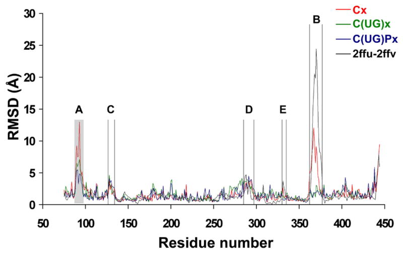
Figure 2.

RMSD per residue calculated for the catalytic domain from simulations starting from the x-ray structure 2FFU in the absence of both substrates (red, trajectory Cx, see Table 1 for notation rule), in the presence of UDP-GalNAc (green, C(UG)x), and in the presence of both UDP-GalNAc and peptide (blue, C(UG)Px), with the GalNAc moiety modeled as in the T10 x-ray structure. The RMSD per residue values between the two x-ray structures of hT2 (2FFU and 2FFV, black line) are also shown. The loop unresolved in 2FFV due to crystallographic disorder is indicated as a shaded area.
