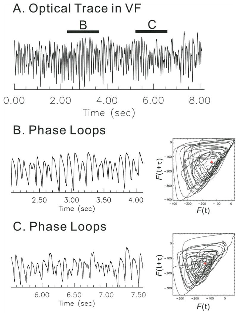
Figure 5.

Phase loops and calculation of phase angle. Calculation of phase was performed using time-embedding methods. A two-dimensional state space was reconstructed from [F(t), F(t+τ)].18 A: Sample trace of a fluorescence Vm signal recorded during ventricular fibrillation (VF). B: Phase loops derived from an interval of VF with large-amplitude Vm oscillations. Phase trajectory consisted of loops rotating clockwise around the origin (red ρ). C: Phase loops derived from an interval of Vm oscillations with small, irregular amplitudes. Note that phase loops fell often outside the origin (red ρ). Time delay (τ) was set to 12 ms.18
