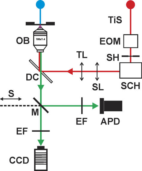
Figure 1.
Schematic diagram of the optical system for two-photon laser scanning imaging and two-photon spot detection. The blue line represents the white light path for bright-field illumination. The red line shows the path of the Ti:Sapphire tunable laser beam (TiS); its intensity is controlled with an electro optical modulator (EOM). In addition, the scan head (SCH), consisting of two orthogonal (xy) galvanometer-based scanners with infrared mirrors, projects the beam through a scan lens (ScL) and a tube lens (TL) to a lateral aperture in the cube turret of the microscope under shutter (SH) control. The green line depicts the emitted fluorescence path. There are two detectors that could be selected with a mirror (M) attached to a slider (S). Emission filters (EF) are in front of each detector. A CCD camera was used for acquisition of bright-field and TPLSM images. In two-photon spot detection mode, fluorescence was detected by an avalanche photodiode (APD) while the laser beam was maintained at a stationary position by the SCH.

