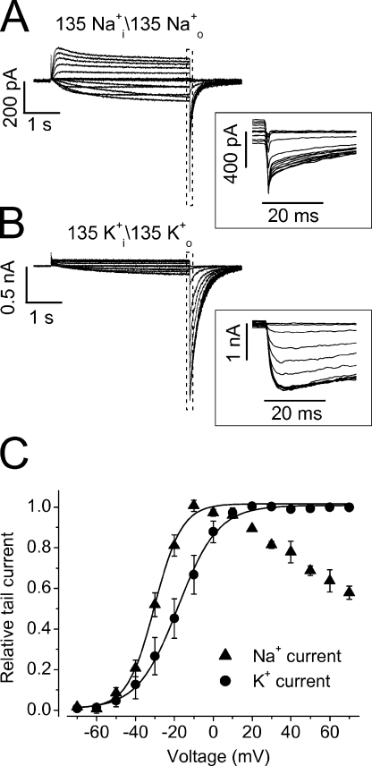
Figure 15.
Comparison of the F627Y Na+ and K+ currents. Families of the Na+ currents (Na+ i/Na+ o 135 mM, A) and K+ currents (K+ i/K+ o 135 mM, B) from F627Y mutant channels. The channels were activated by voltage steps from −70 to 70 mV in 10-mV increments from the holding potential of −80 mV. The cell was then clamped to −80 mV to elicit the tail currents. The portions of the tail currents in the dotted box were expanded in the inset of A and B, respectively. The tail current–activation voltage relationships (g-V) were shown in C. The data points of K+ currents at all tested voltages as well as those of Na+ currents between −70 and −10 mV were fitted to the Boltzmann equation.

