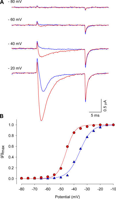
Figure 5.
Effect of Ts1 on S4-DII movement: S660C channel. (A) Superimposed traces of the TMRM-labeled S660C channel in control conditions (blue traces) and in the presence of Ts1 (0.5 μM, red traces), recorded at −80 mV (first panel), −60 mV (second panel), −40 (third panel), and −20 mV (fourth panel). The currents were recorded by applying the voltage protocol described in Fig. 1 A. (B) G-V curves obtained before (blue triangles) and after (red circles) the treatment with Ts1 (0.5 μM).

