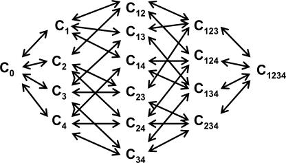
Figure 9.
A general kinetic model for gating in a voltage-gated ion channel. C0 corresponds to the fully deactivated state, with all four S4 segments in the resting position. C1, C2, C3, and C4 correspond to the states where voltage sensors from domains I, II, III, and IV are activated. The numbers in the index refers to voltage sensors that are in activated position. C1234 corresponds to the fully activated state and the open channel form, with all the S4 segments in the activated position.

