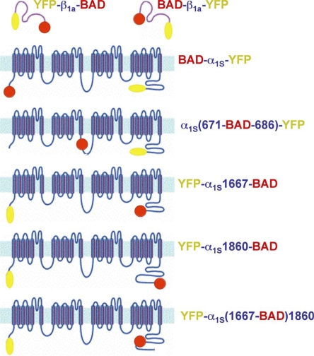
Figure 1.
Schematic illustration of the BAD-DHPR fusion constructs. Constructs are designated by the sites of attachment of BAD (red circle) and YFP (yellow oval). In the α1S II–III loop constructs, α1S residues 672–685 were replaced by the BAD. For the α1S C terminus, BAD was attached after residue 1860, or attached after residue 1667, or placed after 1667 followed by α1S 1668–1860 (YFP-α1S(1667-BAD)1860).

