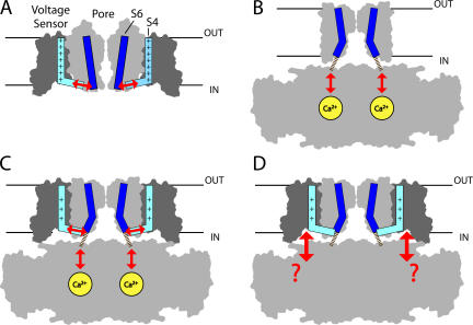
Figure 1.
Proposed pathways of sensor/gate interaction for different channels. (A) Kv1.2, where the charged S4 segment (light blue) in the voltage sensor is proposed to interact with the S6 activation gate (dark blue) in the pore via the S4–S5 linker (arrows). The outlines of the S1–S4 voltage sensor domain and S5–S6 pore domain for two subunits from the Kv1.2 crystal structure (Long et al., 2005a) are shown in dark and light gray, respectively, and are truncated at S1 (protein data bank code 2A79). (B) MthK, where Ca2+ binding to the cytosolic domain is proposed to cause a conformational change that pulls open the gate through short peptide linkers (dashed lines) that are unresolved in the crystal structure (Jiang et al., 2002) (protein data bank code 1LNQ). The attachment points of the linker on the cytosolic domain (in foreground and background) have been altered to better illustrate that linkers are pulled away from the pore axis. (C) A hypothetical BK channel structure formed by appending the Kv1.2 voltage sensors to MthK shows how Ca2+ and voltage may both interact with the gate to have independent effects on activation. The position of the voltage sensors was determined by superimposing the pore domains of Kv1.2 (residues 341–406) and MthK (residues 26–91) in PyMol (http://www.pymol.org). (D) The hypothetical BK channel structure also illustrates the possibility that the large cytosolic domain may interact directly with voltage sensors.

