
Figure 7. RDC-based models for the structure of SDS-solubilized KcsAM.
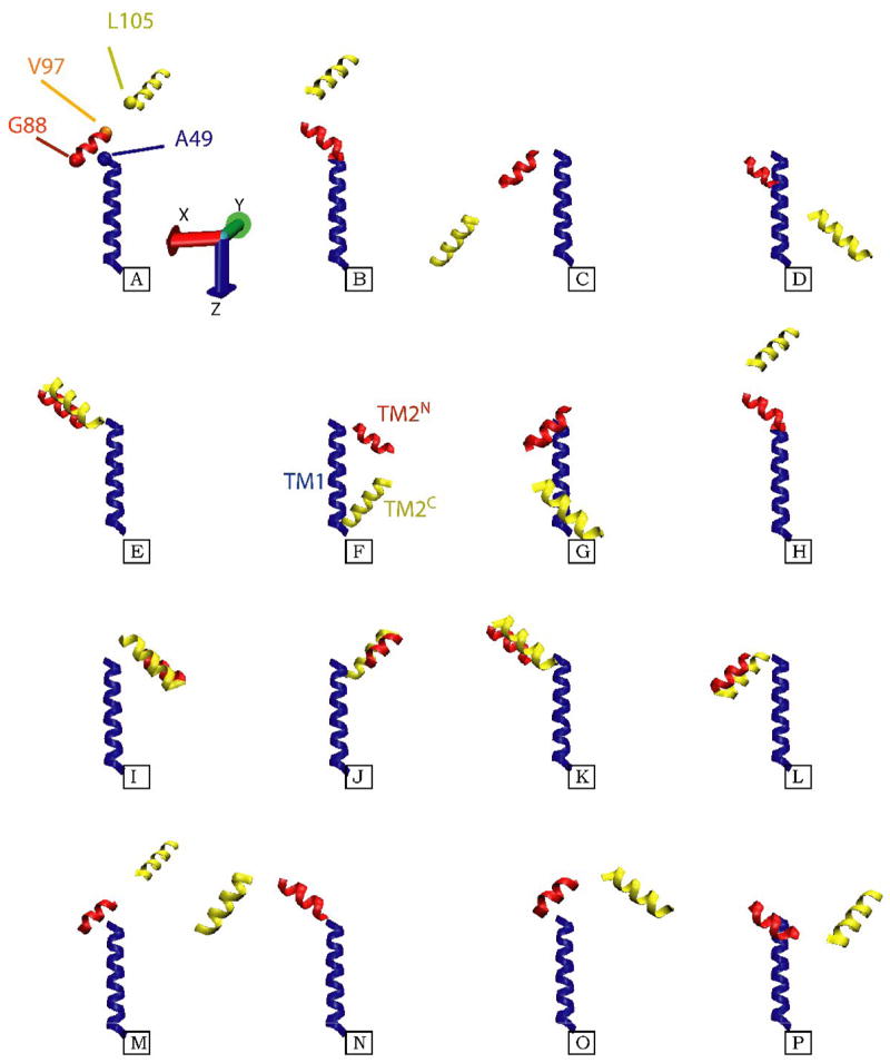
Shown are the sixteen different models for the three TM helical segments of KcsAM, TM1 (blue), TM2N (red), and TM2C (yellow), which are compatible with the acquired RDC data. The TM1 helix is almost co-linear with the z-axis of the alignment frame, and its coordinates are maintained constant in all models. For the upper left structure, the positions of Cα atoms for residues L49, G88, V97, and L105 at the inter-helical ‘joints’ are shown as blue, red, orange and yellow spheres, respectively. Since the data provides no constraints on the translational relation between the three helical fragments, the models were created as follows: 1) The short six-residue linker (TM2K) which connects the two TM2 fragments was appended to each of them in a helical conformation, and the two virtual T101 Cα atoms were superimposed; 2) Since TM1 and TM2N are linked by a solvent-exposed helical segment, residues L49 and G88 have been located on the same side of the SDS micelle. The G88 Cα atom was placed in a plane perpendicular to TM1 and containing the L49 Cα atom, and 7 Å away from the TM1 helical axis. While the position of TM2 is still ill-defined in this procedure, the models shown aim to minimize the radius of gyration and create a relatively compact structure compatible with backbone 15N relaxation and light-scattering data. Of the sixteen possibilities, structures F and G provide the most compact arrangement of the helices, and the former is depicted in the cartoon in Figure 8.