
Figure 5.
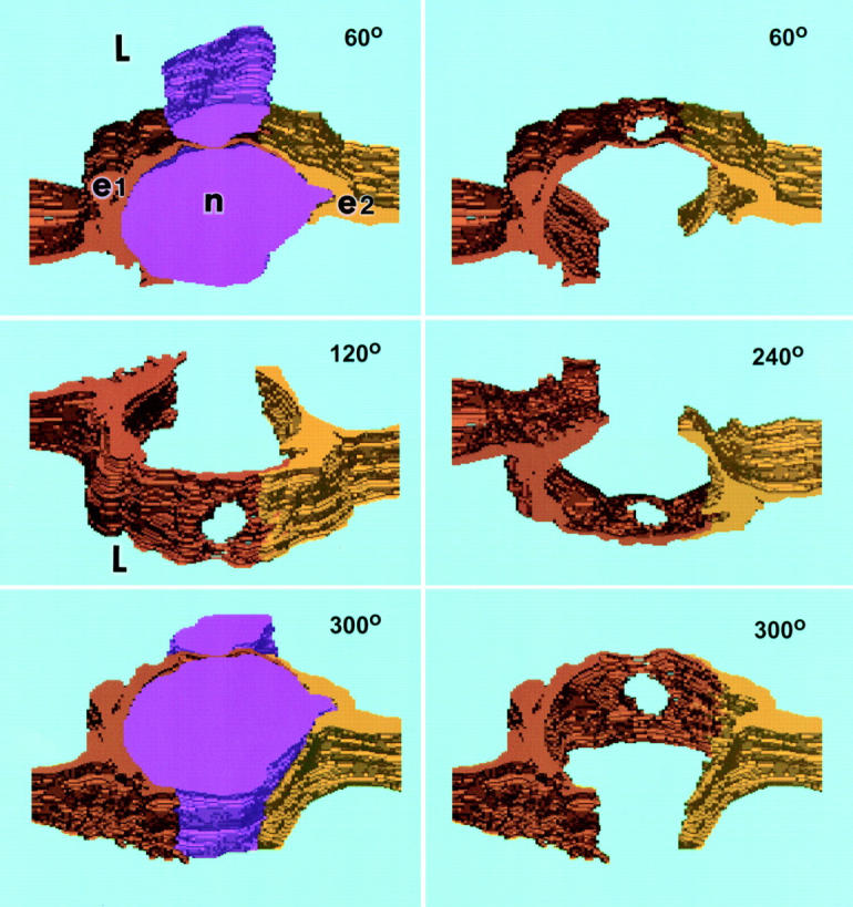
Computer-generated three-dimensional reconstruction of the transmigrating neutrophil illustrated in Fig. 4. The panels portray successive rotations toward the viewer around a horizontal axis at angles of 60°, 120°, 240°, and 300° as indicated. 0° (not shown) would represent a vascular cross section at right angles to the direction of blood flow and 90° (also not shown) would represent a view looking directly down on the luminal surface. Emigrating neutrophil (n), purple, upper and lower left; in the other panels, the neutrophil was subtracted electronically to visualize the pore that passes cleanly through the cytoplasm of EC e1 (orange-brown) distinctly apart from the junction of e1 with e2 (yellow). Cytoplasmic arms of both e1 and e2 embrace the neutrophil luminally and, to a lesser extent, abluminally. L, lumen.