
Figure 5.
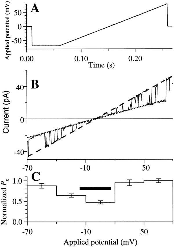
Channel properties of the r-InsP3R-3 in symmetric 0 mM Mg2+ solutions ([Ca2+]i = 80 nM) under a voltage ramp. (A) The applied voltage ramp used to obtain the current traces. (B) I-V relation obtained from a typical current trace using the voltage ramp. Dotted and dashed lines are the fitted closed and open channel I-V relations, respectively. The channel conductance was evaluated as the difference between the slopes of the two fitted lines. (C) Voltage dependence of P o of the r-InsP3R-3 channel. The P o of the channel observed at various Vapp during the voltage ramp was binned and averaged over 28 traces to generate the histogram. SEM of the P o is also plotted. The horizontal bar indicates the voltage range −15 to 15 mV in which channel openings and closings were difficult to discern, so P o was underestimated.