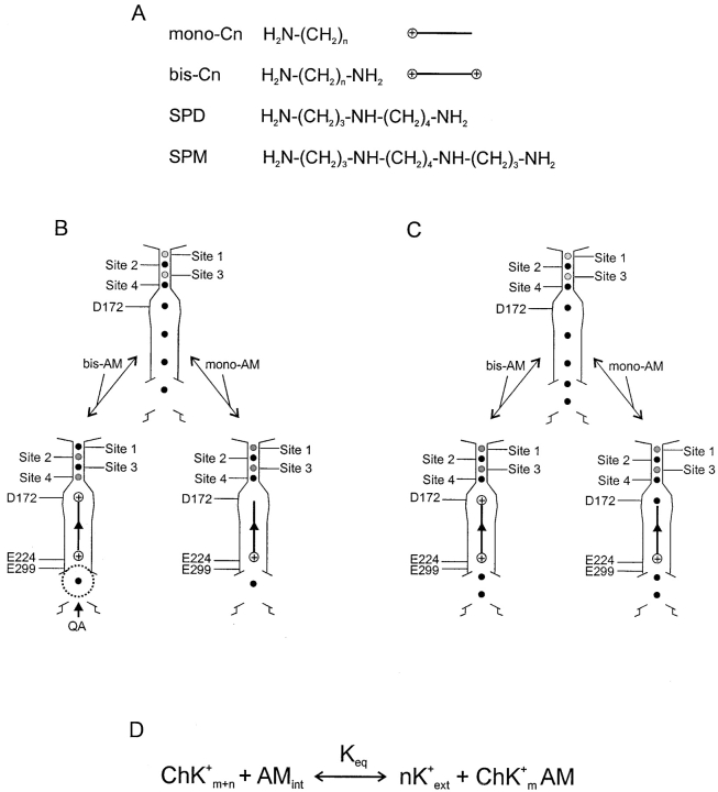
Figure 4.
Blocker structures, channel models, and blocking reaction scheme. (A) Chemical structures of mono-Cn, bis-Cn, SPD, and SPM. (B and C) Models for voltage dependence of channel block by alkylamines. Model B has four K+ ions in the inner pore, and the binding of a blocking amine “pushes” the K+ ions to sites 1 and 3 from sites 2 and 4 in the narrow outer pore (gray versus black dots). The dotted circle at the internal end of the pore represents a blocking QA. Model C has five K+ ions in the inner pore, and the binding of an amine does not affect the binding of K+ ions in the outer pore. The arrowheads midway through the vertical lines that represent the alkyl chains symbolize the fact that these lines represent a series of alkylamines of increasing chain length. (D) One-step steady-state model for channel block by an amine molecule. The total number of K+ ions in a conducting channel (Ch) is m + n. Binding of an intracellular amine (AMint) to the channel pore displaces n K+ ions to the extracellular solution (nK+ ext), and vice versa. The voltage-dependent equilibrium constant (Keq) is defined in the text.

