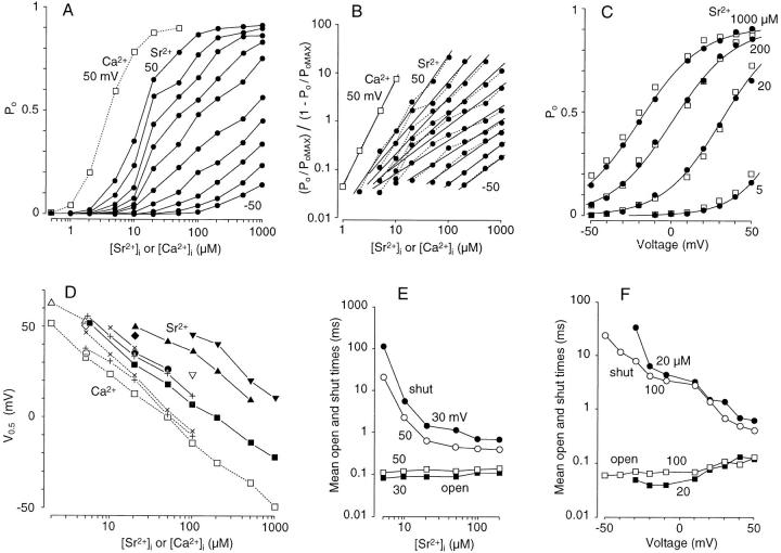
Figure 2.
Analysis of Sr2+-induced activation of BK channels. (A) Dose–response curves. P o is plotted against [Sr2+]i (•) for different membrane voltages (50 to 10 and −10 to −50 mV from top to bottom). For comparison, P o measured with Ca2+ at 50 mV is also shown (□ and dotted lines). (B) Hill plots of BK channel activation. (P o/P oMAX)/(1 − P o/P oMAX) is plotted against [Sr2+]i (•) and [Ca2+]i (□) on a log–log scale for the data shown in A. The slopes are 1.6, 1.3, 1.2, 1.0, 0.83, 0.69, 0.70, 0.79, 0.78, and 0.72 for Sr2+ (+50 to −50 mV) and 2.7 for Ca2+ (50 mV). P oMAX = 0.91. (C) P o is plotted against membrane voltage for activation by Sr2+ (•, 1,000, 200, 20, and 5 μM from left to right) and Ca2+ (□, 200, 50, 5, and 1 μM from left to right). S-shaped curves were drawn using a Boltzmann distribution to fit the plots for each [Sr2+]i, V0.5 and n of which were −22 mV and 1.3, 1 mV and 1.3, 39 mV and 1.4, and 72 mV and 1.6, respectively, from left to right. Plots in A, B, and C were obtained in the membrane patch used in Fig. 1. (D) The half-activation voltage, V0.5, which was obtained from a Boltzmann distribution, is plotted against [Sr2+]i (symbols filled or connected with straight lines) and [Ca2+]i (symbols open or connected with dotted lines) for eight membrane patches, each containing one or two BK channels. Symbols of the same shape indicate the same membrane patch. (E) Mean open (squares) and shut (circles) times measured in a BK channel at 30 (filled) and 50 (open) mV are plotted against [Sr2+]i. (F) Mean open (squares) and shut (circles) times measured in a BK channel at 20 (filled) and 100 (open) μM [Sr2+]i are plotted against membrane voltage.

