Figure 3.
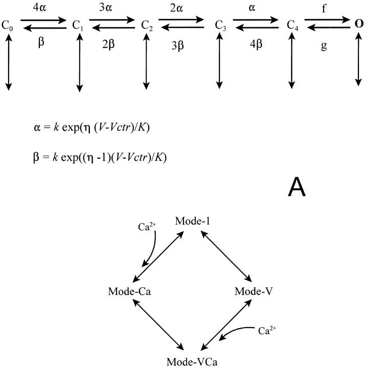
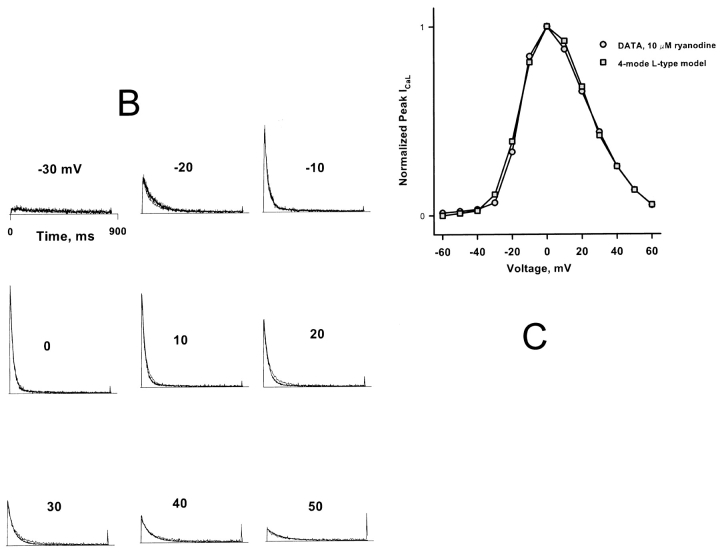
(A) Structure of the scheme of L-type channel gating. The scheme consists of four modes. Each mode (above) consists of a cascade of five closed states connected by movement of four gating charges (horizontal transitions). Openings occur from the rightmost closed state. Each mode has its own center potential and barrier symmetry constants (Vctr and η). Inactivation is due to mode switching (vertical transitions) to modes with bound calcium, left-shifted Vctr, or both (below). “Voltage-dependent” inactivation is actually due to voltage-independent transitions to left-shifted modes, which are strongly favored in the rightward charge states because of the requirements of microscopic reversibility, as suggested by Shirokov et al. (1993). (B and C) Measured L-type currents from a cardiac myocyte in the presence of 10 μM ryanodine are superimposed on simulations with SR release disabled, in the time (B) or voltage (C) domain. Simulated and measured currents were normalized so as to make the peak value of both equal to 1 at 0 mV. The L-type model parameters (Table II) were adjusted “by hand” to achieve the fit.


