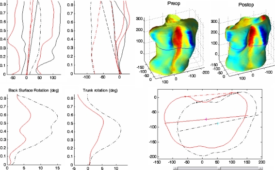
Fig. 6.
Comparative measurements for patient 2. In the top left corner, the right and left mid-lateral and central curves, in frontal and lateral plane. In the bottom left corner, the back surface and axial trunk rotation angle along the normalized trunk height (=1 at the vertebra prominence). In the top right corner, the preoperative and postoperative trunk surface with color corresponding to the depth Laplacian,  where s and t are the parameters of the surface. In the bottom right corner, corresponding cross-sections, with tangents to the back profiles (used to compute the back surface rotation) and principal section axes (used to compute the axial trunk rotation)

