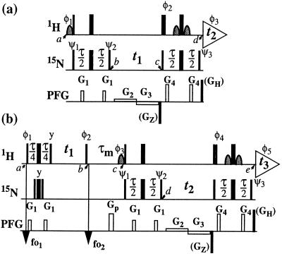
Figure 1.
Schemes for the experiments discussed in this paper. (a) 2D ZQ-[15N,1H]-TROSY. (b) 3D NOESY-ZQ-[1H,15N,1H]-TROSY with transverse relaxation optimization in all three dimensions and suppression of the diagonal peaks. On the lines marked 1H and 15N, narrow and wide bars stand for nonselective 90° and 180° rf pulses, respectively, and curved shapes represent water-selective 90° rf pulses. Water saturation is minimized by returning the water magnetization to the +z axis before data acquisition (15, 18). The time period τ is set to 5.4 ms. The line marked PFG indicates pulsed magnetic field gradients applied along the z axis. (a) The gradients are: G1 amplitude 30 G/cm, duration 1 ms; G2, 5 G/cm, 0.5⋅t1; G3, −5 G/cm, 0.5⋅t1; G4, 40 G/cm, 1 ms. The phases for the rf pulses are: φ1 = {−x}; φ2 = {x}; φ3 = {x, −x, −y, y}; ψ1 = {−x, x, −y, y}; ψ2 = {y, −y, x, −x}; ψ3 = {y}; x on all other pulses. To obtain a complex interferogram, a second free induction decay (FID) is recorded for each t1 delay, with the following different phases: φ1 = {x}, φ2 = {−x}, φ3 = {x, −x, y, −y}, ψ3 = {−y}. After Fourier transformation in the ω2 dimension, the complex interferogram is multiplied by exp[−iΩHt1], where ΩH is the offset in the ω2 dimension relative to the 1H carrier frequency in rad s−1. Further data processing following ref. 2. (b) The gradients are: G1, 30 G/cm, 1 ms; Gp, 40 G/cm, 2 ms; G2, 5 G/cm, 0.5⋅t2; G3, −5 G/cm, 0.5⋅t2; G4, 40 G/cm, 1 ms. The phases of the rf pulses are: φ1 = {4(45°), 4(225°)}; φ2 = {x}; φ3 = {−x}; φ4 = {x}; φ5 = {x, −x, −y, y, −x, x, y, −y}; ψ1 = {−x, x, −y, y}; ψ2 = {y, −y, x, −x}; ψ3 = {y}; x on all other pulses. The 1H carrier frequency offsets are set to 8.7 ppm at time point fo1 and to 4.8 ppm at fo2. Quadrature detection in ω1 is achieved by the States time-proportional phase incrementation method (9) applied with the phase φ2. For each t2 increment, a second FID is recorded with the following different phases: φ3 = {x}, φ4 = {−x}, φ5 = {x, −x, y, −y, −x, x, −y, y}, ψ3 = {−y}. Further data processing as described for a. As an alternative, in both schemes the coherence selection can be supported by addition of the PFGs GZ (−50 G/cm, 1.59 ms) and GH (50 G/cm, 0.177 ms). GZ is then inverted in concert with the phase shifts used to obtain a complex interferogram, and the nonzero initial values for the evolution times need to be taken into account.

