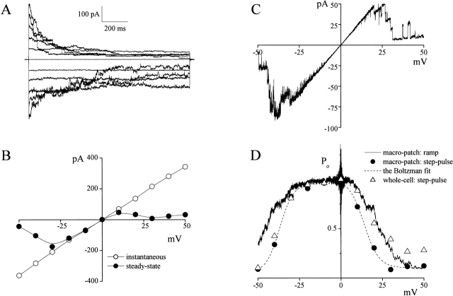
Figure 5.
Voltage-dependent inactivation of large-conductance single-channel currents recorded in macro-patches. (A) Representative current traces recorded upon application of step pulses (1-s duration) from 0 to ±50 mV in 10-mV increments in a macro-patch (containing 20 active channels) excised from a C127i cell. (B) I-V relationship of instantaneous (open circles) and steady-state (closed circles) currents, from the recording shown in A, measured at the beginning and end of current responses to step pulses. (C) Representative steady-state ramp I-V records from a macro-patch (containing five active channels) excised from a C127i cell. A ramp pulse was applied from +50 to −50 mV at the rate of 10 mV/s. (D) Voltage dependence of steady-state open-channel probability. Closed circles represent the ratio of steady-state macro-patch current to instantaneous macro-patch current (from B). Dashed line is the Boltzmann fit for closed circles with V 0 = +13.9 and −36.9 mV for positive and negative potentials, respectively. The solid line represents the ensemble-averaged current of 11 consecutive current responses to ramp pulses as shown in (C). These Po values were calculated as Po = (I/V)/Gmax, where I is the patch current, V is the voltage, and Gmax is the maximal patch conductance at 0 mV. Open triangles represent the ratio of steady-state whole-cell current to instantaneous whole-cell current (from Fig. 1 B, c).

