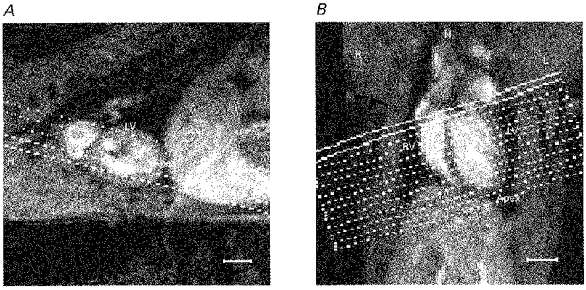
Figure 1. Pilot images.

Sagittal (A) and transverse-coronal (B) pilot images used to establish the cardiac axes and to position the transverse cardiac sections used in the subsequent image analysis. The location of the liver (Liver), left and right ventricles (LV, RV) and the heart apex (Apex) are labelled, as well as the left (L), right (R) and head (H) directions. A, the sagittal pilot MR image showing the orientation of transverse-coronal multislice sections lying parallel to the long axis of the left ventricle (principal cardiac axis) in the plane of the image. B, the resulting transverse-coronal image showing the left and right ventricles most clearly and illustrating the orientation of the principal cardiac axis. The definitive set of 12 cardiac sections is positioned perpendicular to this axis. The scale bars indicate 5 mm. MR pilot images were acquired using the multislice gradient-echo imaging sequence (echo time = 5 ms) with the following parameters: field of view 5 cm for A and 7 cm for B; slice thickness 2 mm; matrix 128 square; repeat time approximately 400 ms.
