Figure 9.
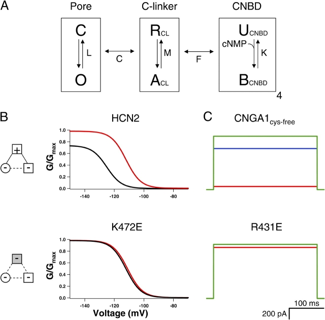
Model of modular gating scheme for HCN and CNG channels. (A) HCN and CNG gating model with three modules: pore, C-linker, and CNBD. Each module is represented by a boxed equilibrium, indicating that each module can be in one of two configurations. Pore can be closed (C) or open (O), C-linker can be resting (R) or activated (A), and CNBD can be unbound (U) or bound (B) with ligand. Equilibrium constants are shown for each module: L for pore, M for C-linker, and K for CNBD. The pore and the C-linker influence each other through allosteric factor C, and the C-linker and CNBD through allosteric factor F. (B) Simulated conductance–voltage (GV) relations for wild-type (top) and K472E (bottom) HCN2 channels in the absence (black) and presence of saturating cAMP (red). A voltage-dependent module that was coupled to the pore was added for these calculations. The values of the parameters used are shown in the materials and methods. (C) Simulated current traces in response to voltages for CNGA1cys-free (top) and R431E (bottom) channels in the presence of saturating cAMP (red), cIMP (blue), and cGMP (green). For the R431E simulations, the current values for cIMP are so similar to cGMP that the two traces overlay. Diagrams to the left show attractive electrostatic interactions by solid lines and repulsive electrostatic interactions by dotted lines with wild-type residues as open symbols and mutant residues as shaded symbols.

