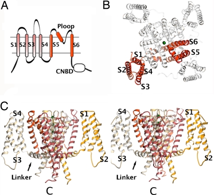
Fig. 1.
Architecture of 6 TM channel. (A) Illustration of a 6 TM channel. The ion pore regions (S5, Ploop, and S6) are shown in red. Also shown are the S1–S4 domain and a C-terminal cytoplasmic domain [CNB domain (CNBD)]. (B) MlotiK1 structure viewed from the extracellular side. One subunit is shown in red. TMs are labeled S1 to S6. Green spheres in the pore are K+. (C) Stereo side view of the MlotiK1 channel structure. Extracellular side at the top of figure. Subunits are shown in different colors. Some of the TMs and the S4–S5 linker are labeled. One of the C termini is indicated by C.

