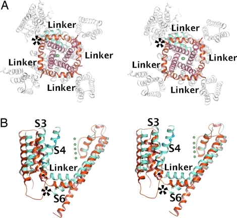
Fig. 3.
The S4–S5 linker and channel gate. (A) Stereoview of cytoplasmic side of MlotiK1 channel with the Kv1.2 subunit superposed via the pore region. In MlotiK1, the S4–S5 linkers and S5 helices are colored red, whereas the C-terminal end of S6 helices is purple. In Kv1.2, the S4–S5 linker, S5, and S6 are colored cyan. The rest of the molecules are colored white. The green spheres represent K+. The asterisk indicates steric clash between the S6 of Kv1.2 and the S4–S5 linker of MlotiK1. (B) Stereo side view of MlotiK1 (red) and Kv1.2 (cyan) subunits superposed via the pore region. The S4–S5 linker and some TMs are labeled. The asterisk indicates steric clash between the S4–S5 linker of MlotiK1 and the S6 of Kv1.2.

