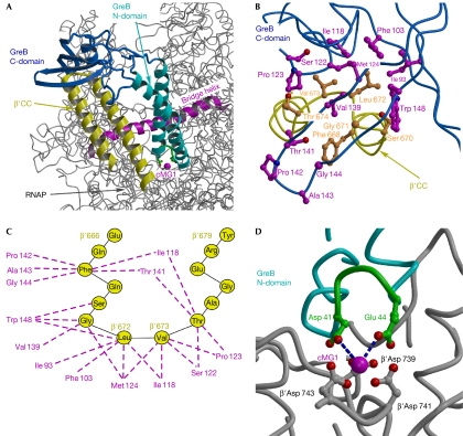
Figure 3.
Structural model of the RNAP–GreB complex. (A) Overall view of the complex. The structure of the Thermus thermophilus RNAP (Vassylyev et al, 2002), in which the β′CC tip residues were substituted for the Escherichia coli counterparts, was used for the modelling. (B) Three-dimensional view of the hypothetical hydrophobic interface and (C) a schematic drawing of possible van der Waals contacts (dashed lines) between the GreB (magenta) and β′CC (yellow) residues. (D) The principal acidic residues (green) at the GreB N-domain tip are positioned at the interacting distance with the active site. The blue dashed lines indicate the shortest distances between the GreB Asp 41 (3.7 Å) and Glu 44 (3.4 Å) and the major (high affinity) catalytic Mg2+ ion (cMG1), suggesting that these side chains would be able to coordinate the second catalytic Mg2+ ion, the precise position of which in the active site of RNAP has not yet been determined. β′CC, β′-subunit coiled coil; C-domain, carboxy-terminal domain; cMG1, a high-affinity catalytic Mg2+ ion in the RNAP active site; N-domain, amino-terminal domain; RNAP, RNA polymerase.

