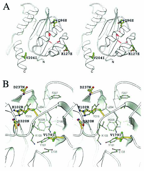
FIG. 7.
Modeled structure of both mutated and unmutated IN2 and RT. (A) Stereo view of the IN2 and INQ96H, K127E, V204I ribbon structure. The ribbon structure was derived from the SIV crystal structure (PDB/1C6V) with Swiss-Model. Residues 96, 127, and 204 are represented by the ball-and-stick illustration, where the green, blue, and red spheres represent carbon, nitrogen, and oxygen atoms, respectively. All bonds of the unmutated IN2 are colored gray, while the overlapping yellow bonds are those of the Q96H, K127E, and V204I mutations. The catalytic triad position on the ribbon structure is shown in red. All diagrams were generated with the program Ribbons (6). (B) Stereo view of the NNRTI binding pocket of RT (PDB1/DLO). The residues of the NNRTI binding pocket are shaded gray, and the atoms are colored as explained above. The thicker bonds shaded in yellow represent the mutated residues R102, I179, N237, and N320, whereas the grayish overlapping bonds represent the original K102, V179, D237, and D320 residues. Residues known to contribute to the NNRTI pocket are depicted in gray, and their atoms and bonds are also displayed in a reduced size.

