
Fig. 3.
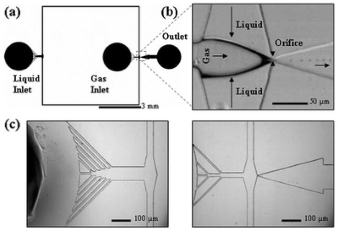
(a) Schematic view of the microfluidic flow-focusing device. All channels have a rectangular cross section and a height of 25 μm. The widths of the liquid and gas inlet channels are {50, 75, 100 μm} and {35, 50 μm} respectively. The devices feature an expanding nozzle with a range of orifice widths {7, 10, 15, 20, 25 μm}. The outlet channel connects to an open reservoir for bubble collection. (b) Main functional area with a 7 μm orifice and 3 μm microbubble generation. The arrows indicate direction of flow. (c) Magnified images of liquid inlet (left) and gas inlet (right) filtering channels.