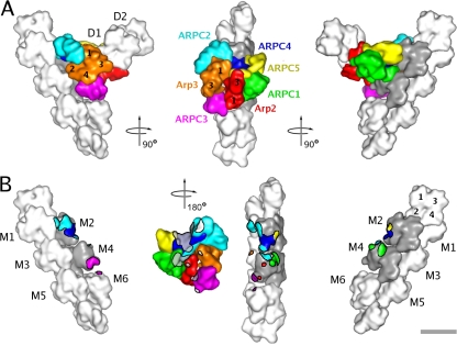
Figure 4.
Low resolution surface representation of the branch junction model. Actin subunits are shown in white or gray. M1–6 are subunits in the mother filament. D1 and D2 are the first two subunits in the daughter filament. Some of the actin and Arp subunits are indicated by numbers. (A) Three different views related by 90° clockwise rotations. (B) The three views of A showing the mother filament with areas of contact with subunits of the Arp2/3 complex color coded according to the subunit coloring in A. In the middle view, the Arp2/3 complex is viewed from the aspect of the mother filament (turned 180° clockwise from A) with points of mother filament contact marked in gray (subunits M2 and M4) and white (subunits M1, M3, M5, and M6). Bar, 5 nm.

