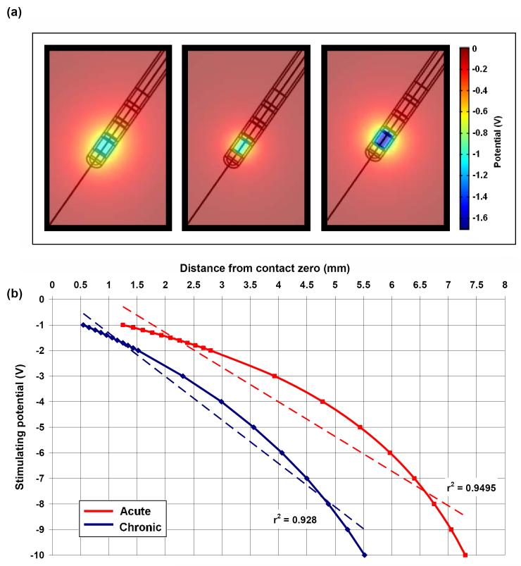
Figure 5.
(a) Potential distribution when the peri-electrode space is filled with ECF (left, -1.0V) and giant cells (centre, -1.0V), and compensatory increase in stimulating intensity of -1.7V in the giant cell case (right, -1.7V) to maintain the same level of stimulation as the ECF case. (b) Comparison of the estimated intensity-distance curves with an assumed activation threshold of 0.5V between ECF and the giant cell cases, with lines of best fit (dashed). In order to compensate for the layer of low conductivity giant cells, the stimulating potential must be topped-up by between 70% and 100%.

