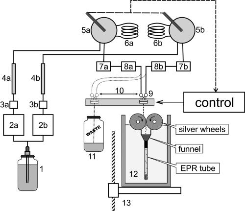
Fig. 5.
Scheme of the freeze-quench apparatus. 1, Vessel with buffer; 2a and 2b, Waters 501 HPLC solvent delivery pumps; 3a and 3b, pressure dumpers; 4a and 4b, reverse-phase HPLC columns; 5a and 5b, Rheodyne 7125 sample injection valves; 6a and 6b, sample loops; 7a and 7b, and 8a and 8b, 5-μm and 0.2-μm inline solvent filters; 9, tangential micromixer; 10, mixer head moving system; 11, waste collection vessel; 12, Dewar with liquid nitrogen; 13, jet length adjusting table. Before the experiment, buffer was degassed on a vacuum line and saturated with argon. Two HPLC pumps (2a and 2b), installed in parallel, are used to deliver the buffer to the micromixer (9). In the purging mode, buffer bypasses the sample loops (6a and 6b), and the free-flowing jet directs to the waste collection vessel (11). In the operational mode, sample loops are included into the flowing path by the sample injectors' valves (5a and 5b), and after a delay, the mixer head (9) moves to the work position and the jet of the mixed sample solution is directed to the cold silver cylinders. The rotating cylinders work as a mill, and the cold sample powder is collected into an EPR tube.

