
Figure 4. Determination of the reversal potential of delayed rectifier current.
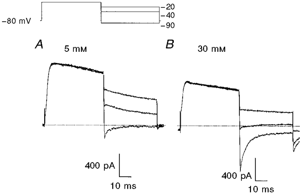
Membrane potential was stepped from -80 to 0 mV followed by test steps to potentials ranging from -15 to -90 mV in 5 mV increments. The inset shows conditioning and three selected test potentials. A, currents recorded during superfusion with a solution containing 5 mM K+. B, currents recorded during superfusion with a solution containing 30 mM K+. The dotted lines mark zero current.