
Figure 1. Location of recording grids.
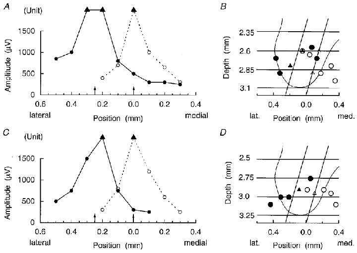
A and C, plots of the maximum amplitudes of motoneurone antidromic field potentials recorded on electrode tracks at different lateral positions (abscissa) in a 16 week cat. B and D, positions for these maxima superimposed on an average outline of the ventral horn as in Kirkwood (1995), together with the grid of recording sites used in each case. The recording sites are represented by the intersections of the two standard electrode tracks for each grid (diagonal lines) with the horizontal lines indicating the standardized depths. ○, dorsal ramus nerves; •, internal intercostal nerves; ▴, ▵, indeterminate field because of the presence of a large potential from a single unit, intracellular or extracellular. A and B, rostral position in the segment; C and D, caudal position in the segment. Arrows on the abscissae of A and C represent the positions of the standard tracks.