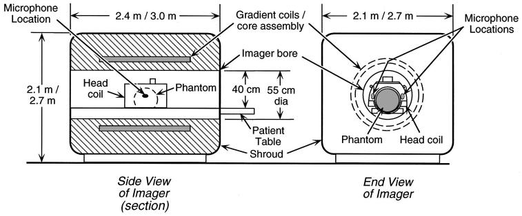
FIG. 1.
Side view (left—in section) and end view (right) of a typical imager showing the gradient coils, bore, and location of microphones for noise measurements. The gradient coils and the cylindrical core on which they are wound surround the imager bore (the cylindrical opening through the center of the imager in which subjects lie during imaging). For noise measurements, a liquid-filled spherical plastic “phantom” (shown dashed in the side view) installed in a head coil was positioned where a subject’s head would be during brain imaging. The measurement microphones appear larger than their actual size (Shure: 4×6×10 mm, Knowles: 3×4×6 mm). Outer dimensions are given for the 1.5-T imager first, then the 3-T imager; bore diameter applies to both imagers.

