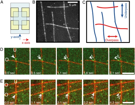
FIGURE 1.
Experimental crossed-flow-path sample chamber and resulting microtubule array. (A) Schematic of crossed-flow-path chamber. The bottom coverglass is 22 mm × 40 mm (pale blue). Four square pieces of double-sided adhesive tape (yellow) are arranged to make two perpendicular 3-mm-wide flow paths. The top coverglass is 18 mm × 18 mm. We denote the flow paths as the x- and y-directions. (B) Example image of rhodamine- and biotin-labeled microtubules bound to the coverglass of a crossed-path flow chamber. Scale bar: 5 μm. (C) Schematic of the same location in B to highlight the crossing microtubule tracks. (D) A single GFP-kinesin, imaged using total internal reflection microscopy, starts walking on the vertical, underpass microtubule (U) and switches to walking on the horizontal, overpass (O) microtubule. (E) A single dynein-dynactin-GFP complex, imaged using total internal reflection fluorescence microscopy, starts walking on the vertical, underpass microtubule (U) and switches to walking on the horizontal, overpass microtubule (O). Green image is GFP fluorescence. Red image is rhodamine fluorescence. Scale bars: 5 μm. See supplementary movies and Fig. S1 for raw images without false coloring.

