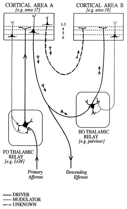
Figure 1.
Schema to illustrate cortical and thalamic pathways. Two thalamic nuclei are shown: a first order (FO) relay on the left and a higher order (HO) relay on the right. A first order relay receives its driver inputs on proximal dendrites from subcortical sources via ascending pathways whereas a higher order relay receives its driver inputs from cells in cortical layer 5 (see ref. 40). The first order relay sends a driver input to layer 4 of cortical area A (thick line), and that same cortical area sends a modulator input (thin line with small terminals onto distal dendrites of the thalamic relay cell) from layer 6 back to the same first order thalamic nucleus. Cortical area A in turn sends a driver input from layer 5 to the higher order thalamic relay. This higher order relay sends its thalamocortical axons (shown as drivers, on the assumption that all thalamocortical inputs to layer 4 are drivers, although empirical data are lacking) to cortical area B and receives a modulator input back from layer 6 of cortical area B. Note that there are two paths by which cortical area A can influence area B. One is the transthalamic path, shown by small arrows and drawn as thick lines indicative of a driver pathway. The other is the direct corticocortical pathway (a “feed-forward” pathway, as defined by ref. 39), and this is shown by small arrows and as alternating thin and thick lines to indicate that we do not know whether this (or any other corticocortical pathway) represents a driver or a modulator input. As one specific example of such circuitry, we indicate the lateral geniculate nucleus (LGN) as a first order relay innervating area 17 and the pulvinar as a higher order relay receiving driver input from layer 5 of area 17 (41) and, in turn, innervating area 18.

