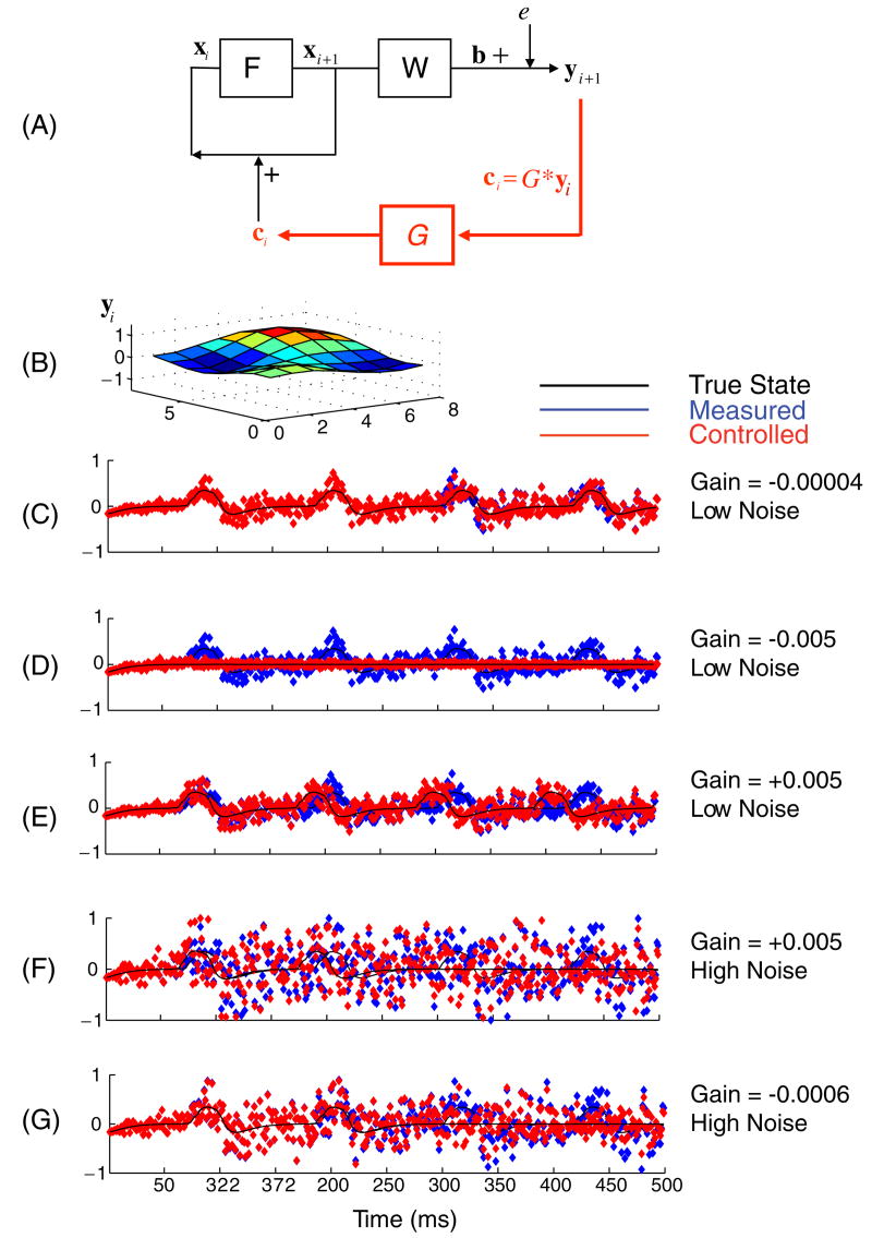
Figure 1.
(A) Schematic of dynamical system F, which acts upon the state variable vector x, and the observation function W which produces the output vector b to which the measurement noise e is added, generating the output observable y. When the direct proportional control is used, the control function G is employed, which generates the control law (ci = G ∗ yi). This control vector is directly ‘injected’ into the neuronal elements, adding vector c to the activity variable u (nothing is added to the unobserved variables a or to the parameters of the system). (B) An instantaneous snapshot of the 8 × 8 output yi during a rotational spiral. (C) The output of the observable y under conditions of small negative gain and low noise, from a single element of the grid in B, shown as a time series without (blue) and with the (red) control applied. The underlying state vector activity element ui is plotted as a thin black line. In contrast with (C), are shown outputs under conditions of higher negative gain and low noise in (D), positive gain and low noise in (E), and high noise conditions with positive and negative gains shown in (F) and (G), respectively. Low noise corresponds to 1–5, and high noise corresponds to 10–14 on an arbitrary scale. Note that under high noise conditions, the application of direct proportional control as illustrated in the schematic renders the system dynamics unstable and destroys the rotational spiral regardless of positive or negative feedback.

